While I was looking at my past research, I thought I still did not understand some main points of wing design. Even though some of my sources talked about them, I never really looked through them, and after looking through several physics forums on wing design while researching what to do for another research project, some familiar yet barely-touched-on topics appeared, such as angle of attack and basic fluid dynamics. So, I did some research on those topics.
Figure 2: Typical Airfoli (Cross-Sectional Shape) of An Airplane Wing
Chord:
Extends from leading edge to trailing edge of the wing
Camber line:
Points halfway between chord and upper wing surface
Angle of attack:
Angle between direction of airflow and the chord
Viscosity is essential in generating lift. The effects of viscosity lead to the formation of the starting vortex (see Figure 4), which, in turn is responsible for producing the proper conditions for lift.
Figure 4: Starting Vortex Formation
As shown in Figure 4, the starting vortex rotates in a counter-clockwise direction. To satisfy the conservation of angular momentum, there must be an equivalent motion to oppose the vortex movement. This takes the form of circulation around the wing, as shown in Figure 5. The velocity vectors from this counter circulation add to the free flow velocity vectors, thus resulting in a higher velocity above the wing and a lower velocity below the wing (see Figure 6).
Figure 5: Circulation of Air Around Wing
Figure 6: Vector Addition Results in a Lower Velocity Below The Wing and a Higher Velocity Above The Wing (WOAH SO COOL)
I found these graphics to be pretty awesome and just what I needed.
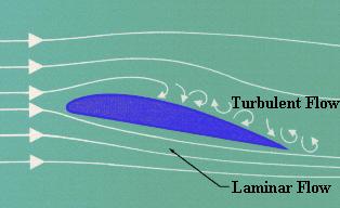
Laminar Flow is the smooth, uninterrupted flow of air over the contour of the wings, fuselage, or other parts of an aircraft in flight. Laminar flow is most often found at the front of a streamlined body and is an important factor in flight. If the smooth flow of air is interrupted over a wing section, turbulence is created which results in a loss of lift and a high degree of drag. An airfoil designed for minimum drag and uninterrupted flow of the boundary layer is called a laminar airfoil.
This is a video I found demonstrating the flow:
At 00:56, it's pretty cool how you can see the flow being disrupted when the pilot stalled!
This website shows the connection between laminar flow and viscosity:
Cool! I finally found the wing design process on the same powerpoint.
As taken from the there:
The design procedure can finally be summarized as follows:
1. Solve the flow equations for ½, u1, u2, u3, p.
2. Solve the adjoint equations for à subject to appropriate boundary conditions.
3. Evaluate G and calculate the corresponding Sobolev gradient ¯ G.
4. Project ¯ G into an allowable subspace that satisfies any geometric constraints.
5. Update the shape based on the direction of steepest descent.
6. Return to 1 until convergence is reached.
And here are some constraints presented when designing:
Fixed CL.
Fixed span load distribution to present too large CL on the outboard wing which can lower the buffet margin.
Fixed wing thickness to prevent an increase in structure weight.
- Design changes can be limited to a specific spanwise range of the wing.
- Section changes can be limited to a specific chordwise range.
Smooth curvature variations via the use of Sobolev gradient.
Today I found a journal article that describes the structural aspects of wing design. This article was especially detailed about the designs of commercial jet wings, but the most interesting I got from the research was information about a specific wing model, F11, and information about its structure and degree of wing deflection.
A separate source I discovered dealt with aspects of wing design also. I got information dealing with wing weight and span influence. As an interesting little fact, the wing box makes up most of the weight of the wing (that probably means it is a big factor in wing design). The weight of the wing is influenced by its thickness, in which the goal of engineering the wing is to decrease it and make sure the wing is consistent in thickness, at least for the wing box.
The above website discusses the use of flaps and slats:
"During takeoff and landing the airplane's velocity is relatively low. To keep the lift high (to avoid objects on the ground!), airplane designers try to increase the wing area and change the airfoil shape by putting some moving parts on the wings' leading and trailing edges. The part on the leading edge is called a slat, while the part on the trailing edge is called a flap. The flaps and slats move along metal tracks built into the wings. Moving the flaps aft (toward the tail) and the slats forward increases the wing area. Pivoting the leading edge of the slat and the trailing edge of the flap downward increases the effective camber of the airfoil, which increases the lift. In addition, the large aft-projected area of the flap increases the dragof the aircraft. This helps the airplane slow down for landing."
Basically, the wing's surface area increases during takeoff and landing to slow down the airplane or increase lift.
It describes flap geometry, aerodynamics, and leading edge devices. This requires an understanding of maximum lift coefficient, which is part of the stalling speed equation.