As of now, my outline for the paper is complete except for the introduction and conclusion. Constructing a claim for the paper will hopefully be not be too difficult since many sources I have looked at emphasize the
importance of several factors when engineering the wing, especially the size and the weight. From a previous post, I found that "the goal of engineering the wing is to decrease it and make sure the wing is consistent in thickness, at least for the wing box." Conclusion will consist of summing up my findings and discussing my thesis.
The difficult part is coming up with ideas for the presentation. I think my best bet for a good presentation now is to let everyone build paper airplanes with different wing designs and have different airplane flying competitions for different criteria, like which one can fly the highest or the fastest. I don't think I can build a wing and actually show everyone wind tunnel testing...I could try with a fan but the presentation would not be as interesting as the paper airplanes...
This was a fun project to work on. I like how I could tie some things I learned in math into this project without having to actually do the math or understand it too deeply. I'll miss doing the research part as I now move on to the actual paper writing...
Monday, April 9, 2012
Sunday, April 8, 2012
Outline: Methods/Processes of Designing
- Methods/Processes
of Designing
- "design by authority" : “One approach to
airfoil design is to use an airfoil that was already designed by someone
who knew what he or she was doing. This "design by authority"
works well when the goals of a particular design problem happen to
coincide with the goals of the original airfoil design. This is rarely
the case, although sometimes existing airfoils are good enough. In these
cases, airfoils may be chosen from catalogs such as Abbott and von
Doenhoff's Theory of Wing Sections, Althaus' and Wortmann's Stuttgarter
Profilkatalog, Althaus' Low Reynolds Number Airfoil catalog, or Selig's
"Airfoils at Low Speeds". The advantage to this approach is
that there is test data available. No surprises, such as a unexpected
early stall, are likely. On the other hand, available tools are now
sufficiently refined that one can be reasonably sure that the predicted
performance can be achieved. The use of "designer airfoils"
specifically tailored to the needs of a given project is now very common.
This section of the notes deals with the process of custom airfoil
design.” (http://www.desktop.aero/appliedaero/airfoils2/airfoildesign.html)
- direct airfoil design: “The direct airfoil design
methods involve the specification of a section geometry and the
calculation of pressures and performance. One evaluates the given shape
and then modifies the shape to improve the performance. The two main subproblems in this
type of method are: the identification of the measure of performance and
the approach to changing the shape so that the performance is improved. The
simplest form of direct airfoil design involves starting with an assumed
airfoil shape (such as a NACA airfoil), determining the characteristic of
this section that is most problemsome, and fixing this problem. This
process of fixing the most obvious problems with a given airfoil is
repeated until there is no major problem with the section. The design of
such airfoils, does not require a specific definition of a scalar objective
function, but it does require some expertise to identify the potential
problems and often considerable expertise to fix them.”
- Indirect airfoil design: “Another type of objective
function is the target pressure distribution. It is sometimes possible to
specify a desired Cp (pressure
coefficient: pressure over the airfoil) distribution and use the
least squares difference between the actual and target Cp's as the
objective. This is the basic idea behind a variety of methods for inverse
design. As an example, thin airfoil theory can be used to solve for the shape of the camberline
that produces a specified pressure difference on an airfoil in potential
flow. The second part of the design problem starts when one has
somehow defined an objective for the airfoil design. This stage of the
design involves changing the airfoil shape to improve the performance.
This may be done in several ways:
1. By hand, using knowledge of the effects of geometry changes on Cp and Cp changes on performance.
2. By numerical optimization, using shape functions to represent the airfoil geometry and letting the computer decide on the sequence of modifications needed to improve the design.”
Wednesday, April 4, 2012
Outline: Wing Design Factors
Today, I continued working on my outline.
- Wing
Designs
- Major
decisions: Wing area/wing loading, Span, aspect ratio, Planform shape, Airfoils,
Flaps and other high lift devices, Twist
- Wing
Area
i.
Restraints affecting wing area: Cruise Drag,
Stall Speed, Take off and landing distance, Maneuver (Instantaneous or
Sustained), Fuel Volume, Hangar size
ii.
Cruise
Drag
1.
Low altitude cruise favors high wing loading and
low wetted area
2.
Higher altitude cruise favors lower wing loading
and greater span.
iii.
Takeoff
and Landing
1.
Increasing wing loading increases takeoff and
landing roll
2.
Roll is proportional to the square of the
takeoff or landing speed
iv.
Maneuvering
1.
Favors low wing loading, particularly for
instantaneous turn rate.
v.
Stall
Speed
1.
Most
light airplanes wings are sized by stall speed requirements
2.
Survivability
vi.
Normally: the smallest
wing area allowed by the restraints
1.
But this is not always
true; sometimes the wing area must be increased to obtain a reasonable lift
coefficient at the selected
cruise conditions, which are critical parts of wing design process
- Wing
Span considerations
i.
Selecting the wing
span is one of the most basic decisions to made in the design of a wing
ii.
The span is sometimes
constrained by contest rules, hangar size, or ground facilities
1.
But when it is not,
use the largest span consistent with structural dynamic constraints (flutter).
This would reduce the induced drag directly
2.
However, as the span
is increased, the wing structural weight also increases and at some point, the
weight increase offsets the induced drag savings.
3.
This point is rarely
reached, though, for several reasons.
a.
The optimum is quite
flat and one must stretch the span a great deal to reach the actual optimum.
b.
Concerns about wing
bending as it affects stability and flutter mount as span is increased.
c.
The cost of the wing
itself increases as the structural weight increases. This must be included so
that we do not spend 10% more on the wing in order to save .001% in fuel
consumption.
d.
The volume of the wing
in which fuel can be stored is reduced.
e.
It is more difficult
to locate the main landing gear at the root of the wing.
iii.
Climb
1.
Induced drag important at climb airspeeds
2.
Greater span good for rate of climb
iv.
Cruise
1.
High altitude: induced drag significant, greater
span preferred
2.
Low Altitude: parasite drag dominates, span less
important
3.
Selecting cruise
conditions is an integral part of the wing design process. It should not be
dictated a priori because the wing design parameters will be strongly affected
by the selection, and an appropriate selection cannot be made without knowing
some of these parameters. But the wing designer does not have complete freedom
to choose these, either. Cruise altitude affects the fuselage structural design
and the engine performance as well as the aircraft aerodynamics. The best CL (lift coefficient) for the wing is not
the best for the aircraft as a whole. An example of this is seen by considering
a fixed CL, fixed Mach design. If we fly higher, the wing area must
be increased by the wing drag is nearly constant. The fuselage drag decreases,
though; so we can minimize drag by flying very high with very large wings. This
is not feasible because of considerations such as engine performance.
v.
Weight
1.
Increasing span and aspect ratio makes the wing
heavier.
2.
Optimum is a compromise between wing weight and
induced drag
vi.
Ground
Handling
1.
Taxiways and runway lights
2.
Hangar size
vii.
Flaps and Slats: "During takeoff and landing the
airplane's velocity is relatively low. To keep the lift high (to avoid objects
on the ground!), airplane designers try to increase the wing area and change
the airfoil shape by putting some moving parts on the wings' leading and
trailing edges. The part on the leading edge is called a slat, while the part on the
trailing edge is called a flap. The flaps and slats move along metal tracks built into the
wings. Moving the flaps aft (toward the tail) and the slats forward increases the
wing area. Pivoting the leading edge of the slat and the trailing edge of the
flap downward increases the effective camber of the airfoil, which increases the lift. In addition,
the large aft-projected area of the flap increases the drag of the aircraft. This helps the airplane slow down for
landing."
viii.
Wing deflection
1.
Large wing structures as they are used
in modern passenger and transport airplanes can not be considered as rigid
anymore. Due to their size and their limited stiffness they have a considerable
deformation when air load is applied. Therefore, during the design phase
special emphasis has to be placed on the aeroelastic behavior of such structures.
Besides the prediction of the deflection and the influence of this deflection
on the aerodynamic behavior and efficiency there is a great necessity to be
able to control the deformation of the structure. This can be realized by a
special distribution and orientation of the structural stiffness, the so-called
aeroelastic tailoring [1], [3]. With the introduction of fiber reinforced
polymers as a light and stiff material in aeronautical applications the
opportunities of aeroelastic tailoring have increased enormously. Now it is
possible to align the direction of the structural stiffness, using a certain
fiber orientation, without the disadvantage of increasing weight due to
additional structural parts [7]. (http://www.dlr.de/fa/Portaldata/17/Resources/dokumente/publikationen/2003/01_anhalt.pdf)
2. affects stability
and flutter mount as span is increased
Friday, March 16, 2012
Outline: Concepts
Today, I read through my sources and tried to organize all the information into an outline for my paper, which I plan to start soon. Here is what I have so far:
- Concepts
- Forces
in flight
i.
Lift
1.
upward force
2.
combination of 2 forces: Newton ’s
3rd law, Bernoulli Effect
ii.
Drag
1.
backward force
2.
a type of air resistance
iii.
Thrust
1.
forward force
2.
generated by propeller, rocket, catapult
iv.
Weight
1.
downward force
2.
caused by gravitational pull
- Lift
and Drag
i.
Can only be seen when there is air moving past
an object
ii.
Bernoulli Effect
1.
Shape & angle of airfoil: force the oncoming
air to curve as it passes the top side of the airfoil
2.
due to the curve: air above the foil moves
faster and farther than the air under the foil
3.
increased speed of air means lower pressure
--> lower pressure on top side of airfoil
4.
--> airfoil is pushed upward
iii.
Third Law
1.
bending airflow: wing redirects the flow of air
downwards --> downward force means there is an equal and opposite force on
the foil, pushing it upwards --> creates lift
iv.
Drag
1.
depends on shape, size, and quality of wing
a.
a thin, streamlined wing will have less drag
than a thick, boxy one
b.
a polished wing will have less drag than a rough
one
v.
Stall
1.
too high angle of attack --> the air flowing
above and below the foil will separate into turbulent eddies
2.
this causes the foil to lose lift and increase
drag
3.
this causes partial or total loss of control
unless the angle of attack is lowered
- Airfoil
Types
i.
High Lift, High Drag
1.
as seen on crop duster planes
2.
pros: extra lift, can take off/land on short
runways
3.
cons: thickness causes a lot of drag --> fly
slowly, cover shorter distances
ii.
Low Lift, Low Drag
1.
as seen in fighter jets
2.
pros: generates low drag; allows for high-speed
movement
3.
cons: because there is not much lift, the
aircraft must move at high speeds in order to keep aloft
iii.
Moderate lift, moderate drag
1.
as seen in small, light propeller aircraft
2.
pros: good for general-purpose aircraft;
inexpensive to build because of the basic, flat-bottom shape of the airfoil
3.
cons: does not allow for high speeds
iv.
moderate lift, low drag
1.
as seen in aerobatic planes
2.
pros: since the airfoil is symmetrical: little
drag, can create lift when flying upside-down
3.
cons: cannot produce lift if angle of attack is
0
v.
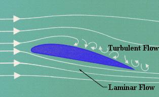
Laminar Flow: is the smooth,
uninterrupted flow of air over the contour of the wings, fuselage, or other
parts of an aircraft in flight. Laminar flow is most often found at the front
of a streamlined body and is an important factor in flight. If the smooth flow
of air is interrupted over a wing section, turbulence is created which results
in a loss of lift and a high degree of drag. An
airfoil designed for minimum drag and uninterrupted flow of the
boundary layer is called a laminar airfoil.
vi.
Angle of Attack:
Angle between direction of airflow and the chord; important because it can
cause lift and drag
Wednesday, February 15, 2012
Back to the Basics
While I was looking at my past research, I thought I still did not understand some main points of wing design. Even though some of my sources talked about them, I never really looked through them, and after looking through several physics forums on wing design while researching what to do for another research project, some familiar yet barely-touched-on topics appeared, such as angle of attack and basic fluid dynamics. So, I did some research on those topics.
Angle of Attack (taken from this website: http://web.mit.edu/2.972/www/reports/airfoil/airfoil.html)
Angle of Attack (taken from this website: http://web.mit.edu/2.972/www/reports/airfoil/airfoil.html)
 |
| Figure 2: Typical Airfoli (Cross-Sectional Shape) of An Airplane Wing |
| Chord: | Extends from leading edge to trailing edge of the wing |
| Camber line: | Points halfway between chord and upper wing surface |
| Angle of attack: | Angle between direction of airflow and the chord |
Viscosity is essential in generating lift. The effects of viscosity lead to the formation of the starting vortex (see Figure 4), which, in turn is responsible for producing the proper conditions for lift.
 | ||||
| Figure 4: Starting Vortex Formation
As shown in Figure 4, the starting vortex rotates in a counter-clockwise direction. To satisfy the conservation of angular momentum, there must be an equivalent motion to oppose the vortex movement. This takes the form of circulation around the wing, as shown in Figure 5. The velocity vectors from this counter circulation add to the free flow velocity vectors, thus resulting in a higher velocity above the wing and a lower velocity below the wing (see Figure 6).
|
Sunday, February 5, 2012
Design Process!
Cool! I finally found the wing design process on the same powerpoint.
As taken from the there:
The design procedure can finally be summarized as follows:
1. Solve the flow equations for ½, u1, u2, u3, p.
2. Solve the adjoint equations for à subject to appropriate boundary conditions.
3. Evaluate G and calculate the corresponding Sobolev gradient ¯ G.
4. Project ¯ G into an allowable subspace that satisfies any geometric constraints.
5. Update the shape based on the direction of steepest descent.
6. Return to 1 until convergence is reached.
And here are some constraints presented when designing:
Fixed CL.
Fixed span load distribution to present too large CL on the outboard wing which can lower the buffet margin.
Fixed wing thickness to prevent an increase in structure weight.
- Design changes can be limited to a specific spanwise range of the wing.
- Section changes can be limited to a specific chordwise range.
Smooth curvature variations via the use of Sobolev gradient.
Wing deflection
Today I found a journal article that describes the structural aspects of wing design. This article was especially detailed about the designs of commercial jet wings, but the most interesting I got from the research was information about a specific wing model, F11, and information about its structure and degree of wing deflection.
Here is the online version of the journal article:
http://www.dlr.de/fa/Portaldata/17/Resources/dokumente/publikationen/2003/01_anhalt.pdf
A separate source I discovered dealt with aspects of wing design also. I got information dealing with wing weight and span influence. As an interesting little fact, the wing box makes up most of the weight of the wing (that probably means it is a big factor in wing design). The weight of the wing is influenced by its thickness, in which the goal of engineering the wing is to decrease it and make sure the wing is consistent in thickness, at least for the wing box.
Here is the website:
http://aero-comlab.stanford.edu/Papers/stanford-aa294.pdf
Subscribe to:
Comments (Atom)